Tuesday, December 15, 2020

Ball signal

The ball signal is a B.E.S.T. (Bollinger Edgerly Scale Trains) model of the Whitefield Junction signal in New Hampshire. The signal is set to allow the narrow gauge to cross the Maine Central track.  The shack is from Portland Locomotive Works and is based on a structure by Sam Swanson. 


The final step on the crossing was installing the guard rails inside the diamond. Like the other guard rails on the narrow gauge track, it was made using plastic rail to avoid electrical shorts.


Saturday, September 5, 2020

Crossing the standard gauge

Track is now installed on the new section, including the broad 21" radius curve in the corner. I use yardsticks with holes drilled at 1" intervals to lay out my curves.  Here one yardstick is clamped to the benchwork to find the center of the curve in the aisle, and another is being used to mark the track centerline.  The shelf to the right is for the staging yard:

Since the Thomaston station is now located within the town itself, instead of outside of town as I originally planned, the railroad would have had to cross the Maine Central Rockport branch east of town. This could make for a neat scene, with a ball signal to control the crossing, so I decided to include it.

For the sake of reliability, I first glued down the narrow gauge track and then built the crossing in place using code 83 standard gauge track and rail. After laying ties made from styrene strip, the track sections were cut to fit and soldered to the narrow gauge track, and then short pieces of rail were cut, bent, and filed to form the guard rails and soldered inside the standard gauge rails. 


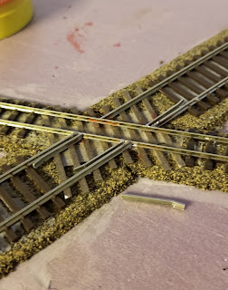
Next the flangeways for the standard gauge were cut into the narrow gauge track using a cut-off disc in a motor tool. Only the head and web of the rail were cut, leaving the base intact to conduct current across the diamond. After cleaning everything up with files and a track cleaner, I got out the rail bus to make sure everything still ran smoothly.   


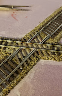
The final step was installing guard rails on the narrow gauge. To avoid creating a short between the two rails (not an issue with the non-operating standard gauge track) I made these with plastic rail salvaged from the Walthers traveling crane kit that I turned into a stationary crane for the transfer track (see previous post here). After the track is painted and ballasted everything should blend together nicely. 


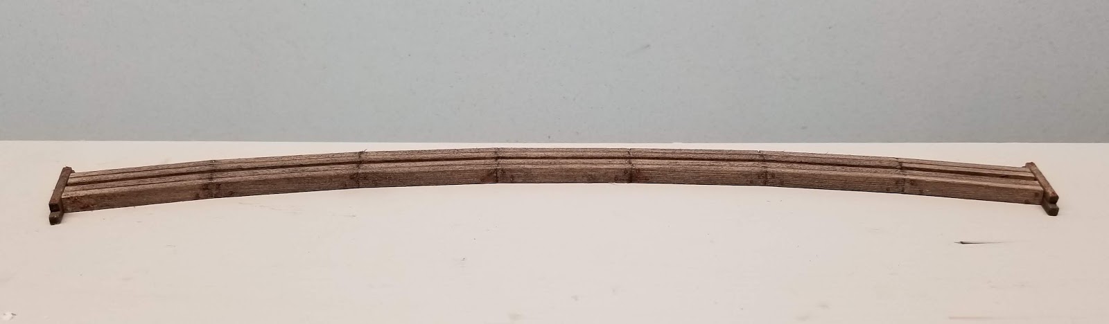
The ball signal and a maintenance shack are almost finished so I will post a mock-up of the entire scene soon.

Wednesday, August 26, 2020

Extending the layout

The Thomaston section has been sitting on my workbench for nearly two years, but I recently moved it back into the train room after finishing the masonite backdrop on the first two walls.  The sky is blended using two Benjamin Moore colors: "aqua marina" at the top blending into "jet stream" at the bottom.  I applied bands of each using brushes and then blended them with a roller leaving a smooth finish with some streakiness suggesting wispy clouds near the horizon.  Later on I will add photo images of trees and other landscape details. 

The backdrop sits on the shelf brackets and isn't actually attached to anything, just sandwiched between the layout and the wall.  I glued 3/4" styrofoam panels to the back of the backdrop in between the shelving standards so that it stands an even distance from the wall all the way around. Screwing the layout sections to the shelf brackets locks everything in place.

Getting the first section back in place motivated me to work on the second section, which is a largely rural area with no sidings. The open-frame benchwork for this section had already been constructed using my usual technique of a 1/2" birch plywood frame and top covered with 2" foam. One thing I learned when building the first section is to avoid having corner curves cross a section boundary, so I added a small extension to accommodate the entire curve in this corner. 

Ultimately the layout will extend along the right-hand wall to a quarry and harbor scene, but for now I plan to install a staging yard to allow me to run trains in and out of Thomaston.

Thursday, April 9, 2020

Trestle construction, part 3

Here’s the finished trestle. The deck/stringer assembly was installed at the same time as the abutments, and the bents were then glued on from below. I used brown ballast as filler around the abutments and the bases of three of the bents, but it will eventually get covered by the final scenery. The last three bents will be “dirted in” whenever I get around to scenicking the creek.


The metal object between the rails is a RibbonRail gauge:


The abutments I made previously turned out to be too narrow for the approach fills. For the shorter abutment on the right-hand end, I was able to remove the top course from the taller abutment to substitute for the smaller one, but I then had to recast the larger (left-hand) one. The original larger casting was repurposed (upside-down) as a retaining wall, which is visible below the transfer crane in the last photo of the November 29 post.

Saturday, December 21, 2019

Trestle construction, part 2


Getting back to the trestle, I installed the crossties on the deck using scale 8’ lengths of 1/16” square basswood, and outer guard rails made from scale 4x8s with NBW castings every three or four ties.


I also got started on the trestle bents, using 1/8” round stock for the piles, 1/8” square stock for the caps, and scale 2x8 for the braces. All of the wood was cut using a cheap 2” miter saw from Harbor Freight, which makes short work of repetitive cuts and ensures that all of the piles are cut at the correct angle, in this case 0, 5, or 10 degrees. The following photo shows the quick-and-dirty assembly jig I used, and a finished bent (with NBWs) in the upper right.


The piles and caps were stained a darker brown than the trestle deck and the braces.  My thinking was that these pieces might have been creosoted while the rest were left untreated. I'm not sure if that is actually prototypical but I like the contrasting wood tones.

Friday, November 29, 2019

A retaining wall for the transfer track

While the trestle is under construction I thought I'd get started on the scenery on the other end of the layout, where there is a transfer track to shift cargo between the narrow gauge and standard gauge.  The narrow gauge track is elevated by a scale 18" to facilitate the transfer, and I wanted a low stone retaining wall to separate the two tracks.  I was going to cast it in plaster like the trestle abutments but decided to try carving it from basswood instead, since I had basswood strips in the right size lying around. The blocks were carved with an X-acto knife and then textured by tapping the strips with a hammer:


Here's a photo taken from the back of the layout showing how the wall looks after painting and installation. It also shows the ballast mix I'm experimenting with, which is two parts "pit run" to one part "NP gray" from Arizona Rock and Mineral.


For the transfer crane, I am using the Walthers "LCL container terminal" gantry crane but placing it on a fixed foundation rather than rails.  In the following photo it is set in place temporarily as it is only half-finished. The kit is designed with metal walkways, which I am covering with stripwood for a more rustic look.


Saturday, November 9, 2019

Trestle construction, part 1

The trestle over the Mill River (which, truth be told, is really more of a creek) will be assembled in place, starting with the stringers and deck and then adding the bents last. Since this is a two-foot-gauge railroad, I only used four stringers, two under each rail.  Each stringer is actually a single length of 1/8” x 3/16” basswood (scale 10x16), but since the trestle is on a 21” radius curve, it should have separate stringers running between each bent and angled to follow the curve.

To mimic this look, I lightly scored the inside face at scale 12’ intervals and then made a deeper cut on the opposite side.  Then I could gently bend each joint slightly without completely breaking it.


The inside stringer was scored at exact 12’ intervals, which is 42 mm in HO, and then the others were scored at 0.5 mm increments (42.5, 43, 43.5 mm) to account for the curve. Each pair of stringers is assembled with short pieces of scale 2x8 as spacers, and then the pairs are glued together with short 1/16" wide spacer blocks. I didn't bother to place the spacers in prototypical locations since they will be hidden by the bridge ties.

After the glue dried I trimmed the ends to length, installed nut-bolt-washer castings, and added short timber retaining walls at each end to hold back the fill at the top of the abutments.


It will be a couple of weeks before I can continue this build, but I'm looking forward to installing the trestle and finally getting started on scenery! And at some point I need to get back to that forney project.