Saturday, December 21, 2019

Trestle construction, part 2


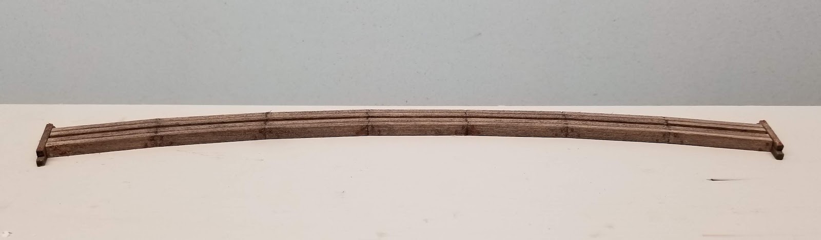
Getting back to the trestle, I installed the crossties on the deck using scale 8’ lengths of 1/16” square basswood, and outer guard rails made from scale 4x8s with NBW castings every three or four ties.


I also got started on the trestle bents, using 1/8” round stock for the piles, 1/8” square stock for the caps, and scale 2x8 for the braces. All of the wood was cut using a cheap 2” miter saw from Harbor Freight, which makes short work of repetitive cuts and ensures that all of the piles are cut at the correct angle, in this case 0, 5, or 10 degrees. The following photo shows the quick-and-dirty assembly jig I used, and a finished bent (with NBWs) in the upper right.


The piles and caps were stained a darker brown than the trestle deck and the braces.  My thinking was that these pieces might have been creosoted while the rest were left untreated. I'm not sure if that is actually prototypical but I like the contrasting wood tones.

Friday, November 29, 2019

A retaining wall for the transfer track

While the trestle is under construction I thought I'd get started on the scenery on the other end of the layout, where there is a transfer track to shift cargo between the narrow gauge and standard gauge.  The narrow gauge track is elevated by a scale 18" to facilitate the transfer, and I wanted a low stone retaining wall to separate the two tracks.  I was going to cast it in plaster like the trestle abutments but decided to try carving it from basswood instead, since I had basswood strips in the right size lying around. The blocks were carved with an X-acto knife and then textured by tapping the strips with a hammer:


Here's a photo taken from the back of the layout showing how the wall looks after painting and installation. It also shows the ballast mix I'm experimenting with, which is two parts "pit run" to one part "NP gray" from Arizona Rock and Mineral.


For the transfer crane, I am using the Walthers "LCL container terminal" gantry crane but placing it on a fixed foundation rather than rails.  In the following photo it is set in place temporarily as it is only half-finished. The kit is designed with metal walkways, which I am covering with stripwood for a more rustic look.


Saturday, November 9, 2019

Trestle construction, part 1

The trestle over the Mill River (which, truth be told, is really more of a creek) will be assembled in place, starting with the stringers and deck and then adding the bents last. Since this is a two-foot-gauge railroad, I only used four stringers, two under each rail.  Each stringer is actually a single length of 1/8” x 3/16” basswood (scale 10x16), but since the trestle is on a 21” radius curve, it should have separate stringers running between each bent and angled to follow the curve.

To mimic this look, I lightly scored the inside face at scale 12’ intervals and then made a deeper cut on the opposite side.  Then I could gently bend each joint slightly without completely breaking it.


The inside stringer was scored at exact 12’ intervals, which is 42 mm in HO, and then the others were scored at 0.5 mm increments (42.5, 43, 43.5 mm) to account for the curve. Each pair of stringers is assembled with short pieces of scale 2x8 as spacers, and then the pairs are glued together with short 1/16" wide spacer blocks. I didn't bother to place the spacers in prototypical locations since they will be hidden by the bridge ties.

After the glue dried I trimmed the ends to length, installed nut-bolt-washer castings, and added short timber retaining walls at each end to hold back the fill at the top of the abutments.


It will be a couple of weeks before I can continue this build, but I'm looking forward to installing the trestle and finally getting started on scenery! And at some point I need to get back to that forney project.


Sunday, October 27, 2019

Trestle abutments

The Mill River trestle will need some stone abutments, so I cast them using lego forms.  The width of the narrowest legos is 26" in HO scale, which is a decent height for abutment blocks. After the plaster set I carved in block lines and gave them a dark wash before shaking them vigorously in a small container with aquarium gravel to polish the edges and give them some more color. The result may be a bit too regular for a narrow gauge road, but I figure that since the railroad's primary customer is a granite quarry, it would have ready access to high-quality stone.


EDIT (November 2):
I eventually decided that the abutment blocks were indeed too regular, in fact they looked more like concrete than granite, so I roughed up the surfaces by tapping them with the tip of a large drill bit and then colored them with weathering powders.  Here's a comparison - the one with the new treatment is on the right:


Saturday, October 19, 2019

Painting track

After masking the turnout points and spray painting all of the track brown, I tried a few techniques to paint and weather the ties. I have read that the Maine two-footers used untreated (non-creosoted) ties, which calls for a sun-bleached and weathered look. The following photo shows the steps I used: from left to right, drybrushing with white paint, then a heavy india ink/alcohol wash followed by dusting with tan weathering powder from Monroe Models. I applied the powder too heavily, but compensated by scraping the ties to give them some texture, followed by a light application of white powder to the ties to fade them, and finally applying dark rust powder to the spikes and tie plates.


Here's a closer shot of the finished section, temporarily buried in aquarium filter charcoal to approximate the cinders that I plan to use in the engine terminal area. It looks pretty good to my eye so I'll continue using this approach on the rest of the track.


Tuesday, October 15, 2019

Layout update

Installing the turntable inspired me to finish laying the track on the Thomaston section. To avoid having a section joint right in the middle of the engine terminal, I added a 42" long extension at a right angle to give a 9' long L-shaped section that will include the roundhouse, the car shed (the short spur in front of the roundhouse tracks), and a trestle across Mill River to the east of town.  I had originally imagined that the railroad would terminate outside of town to avoid having to cross this river (see August 2017 post), but since I wanted a trestle anyway, I decided to relocate the depot and engine terminal within the town borders.

Here's a photo of the full section. I took it it outside to paint the track:


The 9' length is a little unwieldy, but the layout is meant to be semi-permanent and it is a major advantage to not have the roundhouse tracks cross a section joint. This section is also light enough that I could imagine displaying it at shows as a standalone switching layout.

I am using traditional two-cab DC for this layout since it is difficult to jam DCC decoders into HOn30 locomotives, especially the forneys which don't have a separate tender, and I seriously doubt I will ever need to run more than two trains at the same time.  This section is divided into three blocks: one for the back track and engine terminal, one for the front track, and one for the track that crosses the creek.  Power to the two spurs is controlled by their corresponding switches, and the roundhouse tracks are selected by a rotary switch.

Here's a shot of the underside showing the wiring, switch machines, and turntable mechanism:


Sunday, September 8, 2019

Turntable mechanism

A while ago I posted a series of photos showing the construction of a turntable for Thomaston. I installed the pit on the layout but ran into “analysis paralysis” when I couldn’t decide whether to motorize the turntable or rig up a manual control mechanism. I finally decided on manual, since my preference is to use manual controls wherever that would have been the case in real life (turnouts, uncoupling, etc.). The breakthrough came when I found a set of gears and a rotating turntable brick in an old box of legos:


The lego turntable brick has a 1/8” bore, so I epoxied some eighth-inch brass tubing into the bottom of the turntable, making sure that it was perfectly perpendicular:


The gears have a 3/16” bore, so I bent some 3/16” steel rod to make a crank. The white gear is attached to a 4x4 lego brick bored at 11/64” to give a press fit on the shaft in case I need to adjust it. In the photo below you can also see the pin that runs through the vertical turntable shaft and engages the nubs (the official lego term is “studs”) on the blue gear. The baseplate is still taped in place because I’m still adjusting everything to be centered and level – a surprisingly finicky process.


The mechanism turns smoothly with very little slop, but can be disassembled in seconds if I need to remove the turntable in the future. And the total cost was $3!